PE-Load Prep User Guide
This guide describes how to create and run a load simulation project with PE-Load Prep. The first steps are explained here:
Before being able to create the first jobs you need to set up the following properties:
To further adapt PE-Load Prep to your own needs you can specify in detail how the simulation models will be parametrized and create your own DLC definitions:
At last the following chapters describe how to create and simulate jobs:
Introduction
The load simulation of wind turbines requires us to run many hundred or thousands of individual simulations. Each of these simulations are controlled by a set of parameters that make the simulation run unique. How the parameters are set in each simulation run is determined by recognized standards such as IEC 61400-1. Setting the parameters manually is obviously cumbersome, especially when many of the parameters are determined by the standard requirements in the first place.
To use PE-Load Prep, we need a working aeroelastic model first. After defining the standard’s requirements and how our simulation model should behave in different design situations, PE-Load Prep creates a simulation environment by
creating an organized folder structure for each job and job groups,
writing all parameters into the respective input files for each individual job,
allowing us to run and repeat all simulations or subsets thereof,
monitoring the simulations and giving us feedback about the success or errors that occurred.
Getting Started
On starting PE-Load Prep you have to connect the application with the PE-Load Prep database in the dialog Database Properties. Afterwards the dialog Settings will be shown in which you can edit the global settings of PE-Load Prep.
Database Properties
In the dialog Database Properties you have to enter the following credentials to verify your user license and to connect the application with the PE-Load Prep database.
Database: Name of the deployed database.
Host: Name / IP of the database server.
Port: Port number of the server.
User: User name with which you want to connect to the database.
Password: Password for User.
To edit the Database Properties at a later point go to File -> Connect to Database. In the following dialog Settings the global properties of PE-Load Prep can be edited.
Note
After submitting your credentials in Database Properties PE-Load Prep will verify your license via the PE-Load Prep license server. This process requires a working internet connection.
Settings
To edit the Settings of PE-Load Prep go to File -> Settings. Following options are available:
Use Scratch Folder for Simulation: Set checked if you want run the simulation in a different directory than Root Path. After finishing the respective job all model and result files will be copied back to the original folder.
Reuse Wind Fields: Set checked if you want to reuse the results of already simulated wind Job Tasks for Analysis Jobs that have either the same random seed and / or the same wind parameters.
Scratch Folder Path: Path to scratch folder. Only required if Use Scratch Folder for Simulation is checked.
Wind Field Folder Path: Path to directory where wind fields will be stored. Only required if Reuse Wind Fields is checked.
TurbSim.exe Path: Path to .exe-file of TurbSim. Only required if Simulation Software ADAMS, OpenFAST, FAST7 or FAST8 is used.
IECWind.exe Path: Path to .exe-file of IECWind. Only required if Simulation Software ADAMS, OpenFAST, FAST7 or FAST8 is used.
ADAMS-From_LAM.bat Path: Path to From_LAM.bat-file that is used to run ADAMS in batch mode. Only required if Simulation Software ADAMS is used.
Flex5.exe Path: TBA: Path to .exe-file of Flex5. Only required if Simulation Software Flex5 is used.
Fast7.exe Path: TBA: Path to .exe-file of FAST7. Only required if Simulation Software FAST7 is used.
OpenFast.exe Path: Path to .exe-file of OpenFAST. Only required if Simulation Software OpenFAST is used.
Fast8.exe Path: TBA: Path to .exe-file of FAST8. Only required if Simulation Software FAST8 is used.
Bladed.exe Path: TBA: Path to .exe-file of Bladed. Only required if Simulation Software Bladed is used.
Max Nr. of Simulation Threads: Maximum number of simulation tasks (Job Tasks) that can be processed simultaneously. (see Job Queue)
Interval for Checking Job Queue (in s): Specify how often PE-Loads Prep checks if a new Job Task can be simulated in Job Queue.
Simulation Kill Time (in s): Specify how long PE-Load Prep waits until a Job Task that has 0% CPU usage will be terminated.
Analysis Plan
A simulation project is reflected in an Analysis Plan in PE-Load Prep. The Analysis Plan combines sets of parameters for a turbine model and external conditions with a standard definition, i.e. the definition of load cases. From these definitions, PE-Load Prep derives simulation jobs. You can control how PE-Load Prep works through these load cases. It is possible to select only certain jobs to run first, either individually or by load case group.
To create an Analysis Plan go to File -> New Analysis Plan in the menu bar. The Analysis Plan user interface consists of 5 elements:
Workflow: Navigation bar representing a standard workflow in PE-Load Prep.
Analysis Plan Properties: General properties that apply to the whole Analysis Plan. Apart from numeric values like Power Law Exponent most of the properties consist of parameter sets called Assets like Turbine, Turbine Class, etc. that are assigned to the Analysis Plan.
Asset Properties: Properties of the assets Turbine, Turbine Class, Turbulence Class and all Master File Paths assigned to Analysis Plan. This window will be shown after the Analysis Plan Properties are set up and the Analysis Plan is created.
Jobs: Displays all created jobs.
Job Queue: Used for simulation and monitoring of Job Tasks.
To show / hide any of the listed elements go to View in the menu bar. To open already existing Analysis Plans go to File -> Open Analysis Plan in the menu bar. In the following dialog you can open and delete any Analysis Plan in the database PE-Load Prep is currently connected to. To make a copy of the Analysis Plan and continue working with the copy go to File -> Save Analysis Plan as in the menu bar. To close the Analysis Plan File -> Close in the menu bar.
Note
When an Analysis Plan is saved with ‘Save Analysis Plan as’ the corresponding Analysis Jobs, Initialization Jobs, and Job Tasks will not be copied to the new Analysis Plan.
Workflow
The Workflow window serves as a navigation bar that represents a typical workflow for a Analysis Plan in PE-Load Prep. It can be hidden / shown under View -> Workflow. The steps displayed in Workflow are divided into three stages:
Properties: Set up properties and assign Assets. This will affect the whole Analysis Plan.
Parameters: Customize job specific and / or DLC specific parameters. This might only affect jobs of certain DLCs.
Jobs: Create and simulate jobs based on the input made in Properties and Parameters.
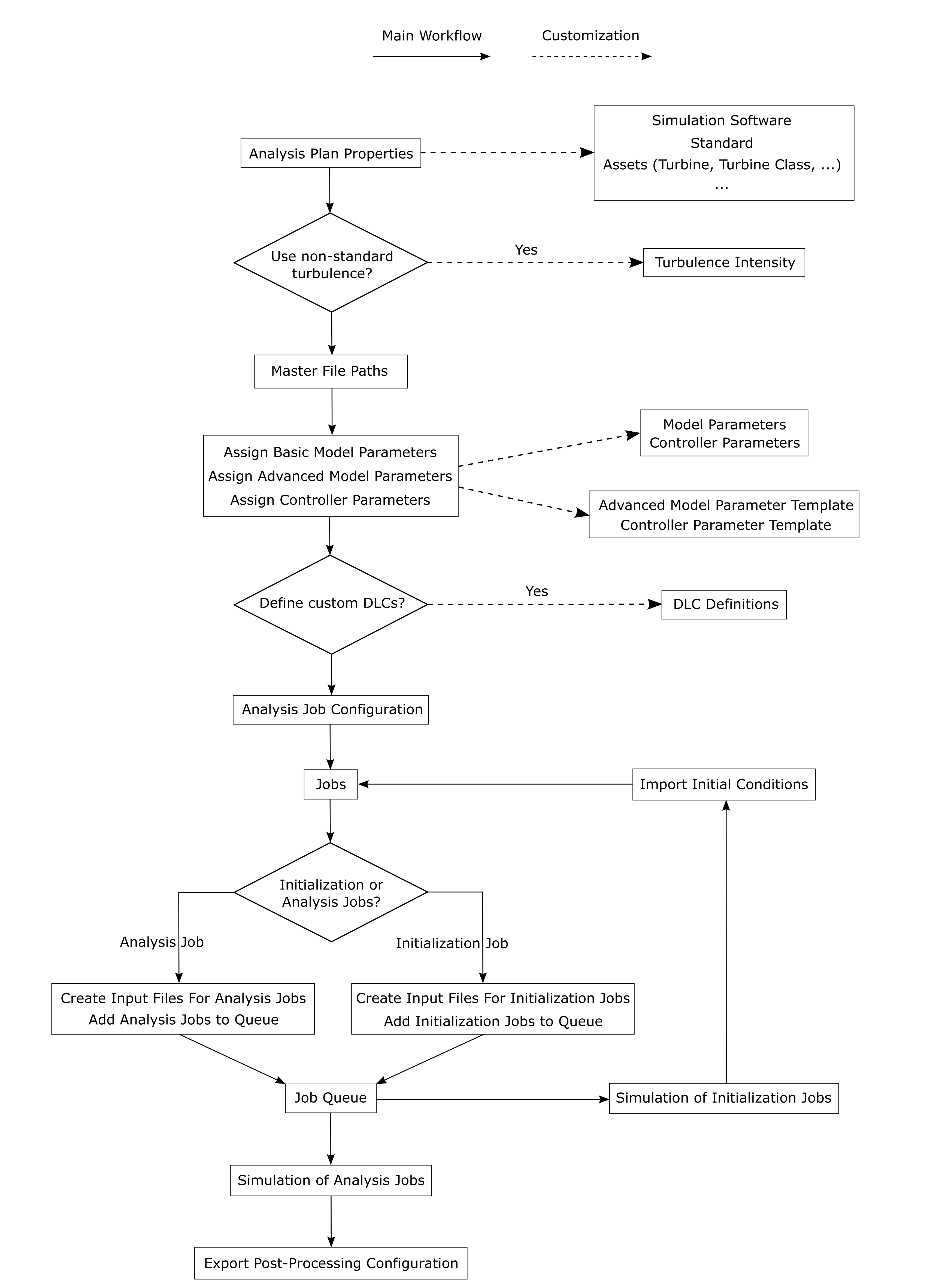
A typical PE-Load Prep Workflow
In the following, a typical workflow of PE-Load Prep is described. The first step is to set up the Analysis Plan Properties. You need to specify parameters (e.g. Vhub Increment) and sets of parameters (called Assets, e.g. Turbine) that will affect all individual jobs in the Analysis Plan (see General Conditions). Existing Assets can be edited before you assign them to the Analysis Plan or you can create your own ones. After successfully setting up the Analysis Plan Properties the Analysis Plan will be created and saved in the database. Now the window Asset Properties will be shown in which you can revise the Assets Turbine, Turbine Class and Turbulence Class that you have assigned to the Analysis Plan and edit them subsequently if necessary. Likewise, in the dialog Turbulence Intensity the turbulence intensity values that have been calculated for every wind speed bin based on the input in Analysis Plan Properties can be revised and edited if necessary.
As a next step you have to specify the File Paths for the Master Files, that serve as templates for the model input files.
By now you have completed the first stage of setting up global properties for the Analysis Plan. You could now already create the first jobs and start simulations, but you will usually need the additional parametrization features provided by PE-Load Prep to fully define your load cases. In the dialogs Assign Basic Model Parameters and Assign Advanced Model Parameters you can define and edit the Basic Model Parameters and Advanced Model Parameters respectively. Both Basic Model Parameters and Advanced Model Parameters address the wind conditions for the wind field generation and information regarding the mechanical model. While the Basic Model Parameters have a global scope the Advanced Model Parameters are DLC-specific. Note that editing the Basic Model Parameters is usually not required if they have been properly set up for the simulation software you want to use in your Analysis Plan. The Controller Parameters address the controller model and are defined and edited in Assign Controller Parameters.
After you have defined the parameters, you can proceed to create your first jobs. In the dialog Analysis Job Configuration, you can choose from a list of DLCs defined in your selected Standard. After you have selected one or more DLCs, PE-Load Prep will automatically create the respective Analysis Jobs and Initialization Jobs based on the Standard. The Standard and its DLC Definitions can be customized beforehand. The created jobs and their most important properties are displayed in window Jobs.
By now you have a list of created jobs that are defined by the Analysis Plan Properties, the assigned Assets and the DLC Definitions and will be parametrized according to your setup of the Basic Model Parameters, Advanced Model Parameters and the Controller Parameters. In the dialogs Create Input Files for Initialization Jobs and Create Input Files for Analysis Jobs you can now create model input files for these jobs. PE-Load Prep will then create a directory (under the directory Root Path) for every designated job, copies the files defined in Master File Paths into every of these directories and parametrize them based on the job definitions.
You can find the appropriate initial conditions for your simulation model using Initialization Jobs before starting the main simulation. To calculate the initial conditions for the Analysis Jobs based on the results of the Initialization Jobs go to Jobs -> Import Initial Conditions. PE-Load Prep will then automatically extract the initial conditions and add them to the definitions of the respective Analysis Jobs. If you now create the input files for these Analysis Jobs and add them to the Job Queue (go to Create Input Files for Analysis Jobs and Add Analysis Jobs to Queue), they are going to be simulated using suitable initial conditions.
Next, you can use the Job Queue to manage and start the simulation process. In Add Initialization Jobs to Queue and Add Analysis Jobs to Queue you can send designated jobs to the Job Queue. To start the simulation process go to Start Queue. The status window of the Job Queue enables you to monitor the progress.
Finally, you can export your post-processing configuration to PE-Load Post via Jobs -> Export Post-Processing Configuration.
Note
The illustrated workflow is just a recommendation. PE-Load Prep allows the user to deviate from this default workflow and use their own approach. E.g. if you have existing Analysis Jobs and subsequently make changes to the Analysis Plan Properties, DLC Definitions, Controller Parameters, etc. those already existing Analysis Jobs will be altered according to the changes. Note that input files and Job Queue entries that already exist for the affected jobs won’t be altered automatically, you have to recreate them to apply the changes.
Analysis Plan Properties
The Analysis Plan Properties determine essential settings for the Analysis Plan such as the Simulation Software and the Standard definition to be used. Furthermore you can make use of so called Assets which are sets of values for parameters that represent internal and external conditions for the turbine simulation. They organize the parameter values logically in a way that they can be seen as templates. For instance, values that depend on a turbine design are allocated to the Asset Turbine so that the turbine can be reanalysed with different external conditions or a different controller template. Therefore Assets can be seen as source material for the parameters to use when PE-Load Prep determines their value.
In the window Analysis Plan Properties the user defines these properties and Assets:
Analysis Plan Name: This is the name of the Analysis Plan. It is used to distinguish different Analysis Plans from one another and to name the folder into which all jobs are written during job creation.
Simulation Software: Indicates which simulation software is used to run the simulations. This controls the sets of Basic and Advanced Model Parameters used in the DLC Definitions, i.e. the parameter ‘language’ and how to process it. In addition, the simulation workflow and programs to run (e.g. wind generation tool, aeroelastic code, etc.) are controlled by this parameter.
Standard: The Standard is a pre-defined set of DLC Definitions. These DLC Definitions are independent of the Simulation Software used. By adding Advanced Model Parameters to a DLC for multiple Simulation Softwares, a Standard can be run using different simulation codes. The Standard can be used by multiple Analysis Plans, edited or entirely new Standards can be created by the user.
Turbine: The Turbine is a set of parameters that are used for the DLC Definition and that depend on the design of the wind turbine.
Turbine Class: The Turbine Class defines the reference wind speeds for the Analysis Plan.
Turbulence Class: The Turbulence Class defines the reference turbulence intensity for the Analysis Plan.
Vhub Increment: The parameter defines the step size to be used in the discrete distribution of wind speeds for load cases in which a wind speed range shall be considered. That means that for a Vhub Increment of 1 m/s, for normal production load cases, Analysis Jobs will be created in steps of 1 m/s starting from v_in ending at v_out, where for each wind speed the required number of jobs will be considered.
Power Law Exponent: Power Law Exponent to be considered in the wind field generation. The Power Law Exponent is usually passed to the wind field generation tool as a Basic Model Parameter. The Power Law Exponent is used for all jobs in the Analysis Plan. Hence, overrides of this value (e.g. for the EWM) must be considered in the wind field generation tool (e.g. through the Wind Model identifier).
Vertical Inflow Angle: Vertical Inflow Angle to be considered in the wind field generation. The Vertical Inflow Angle is usually passed to the wind field generation tool as a Basic Model Parameter. The Vertical Inflow Angle is used for all jobs in the Analysis Plan.
Pitch Deviation: Defines a set of fixed pitch angle offsets to be applied to the aeroelastic model.
Controller: The Controller is a pre-defined set of controller parameters that can be edited by PE-Load Prep when Analysis Jobs are created. The Controller Parameters can be assigned to DLC groups in the Assign Controller Parameters interface. In the Controller, the identifiers (keys) and the syntax to find the respective values are defined. The Controller Parameters are independent of the Simulation Software, the Turbine and the Analysis Plan used. The selection of a Controller only determines the set of Controller Parameters that are available for assignment later on.
Simulation Time Template: The Simulation Time Template is a pre-defined set of allocations of time-related parameters to DLC groups. Each Standard requires a fully defined Simulation Time Template for the creation of Analysis Jobs.
Post-Processing Template: The Post-Processing Template is a pre-defined set of allocations of post-processing-related parameters to DLC groups. These parameters can be used to create an interface file for PE-Load Post for easier configuration of the post-processing. The Post-Processing Template and the related parameters are entirely optional.
Root Path: The working directory for the simulation project. All folders and files created by PE-Load Prep will be stored in a structure in the working directory.
The window Analysis Plan Properties can be hidden / shown under View -> Analysis Plan Properties or Analysis Plan Properties in window Workflow.
Analysis Plan Name
The Analysis Plan Name helps you identifying your simulation project. It is also used as a file name for the main model file and the project folder in your disk.
Note
The main model file is often passed as an input argument to the simulation software. It is possible that your simulation software will fail to execute when the file name contains special characters, so you have to keep this in mind when choosing the Analysis Plan Name.
Simulation Software
The Simulation Software controls what parameters are used by PE-Load Prep, how they are handled, and in what Master Files they are found. Basically, these settings tells PE-Load Prep in what language it needs to speak in your simulation project.
The Basic Model Parameters are automatically set for the respective Simulation Software, but can be edited or expanded later. In addition, PE-Load Prep will only let you work with Advanced Model Parameters that work with the selected Simulation Software in the Analysis Plan. Because the Controller Parameters depend only on the Controller assigned to the Analysis Plan, they are unaffected by the choice of the Simulation Software.
You have to choose a Simulation Software from a pre-defined list. At the moment, it is not yet possible to add a new Simulation Software via the GUI.
Standard
The Standard acts as a template for sets of parameters that are organized in load case groups. The terminology used follows the style of IEC 61400-1. There are two types of Standards: IEC and GL. The Standard Type determines how the turbulence intensities are calculated for the NTM and the ETM for the respective standards.
In the dialog Standard you can either select a pre-defined Standard, or set up your own Standard. Furthermore you can edit, delete and copy Standards. Note that when deleting and copying a Standard the Assets mentioned above (with the exception of Turbine and Turbulence Class) will be deleted and copied as well (in the latter case the user can choose if he wants to copy the Controller Parameter Templates and Advanced Model Parameter Templates associated with the Standard).
The definitions of the load case groups and their parameter variation can be customized for the currently assigned Standard in DLC Definitions.
Controller
The controller model determines the behaviour of the pitch and the generator controller. It is usually parametrized by a configuration file whose definition and structure depends on the controller type. To let PE-Load Prep know with which type of controller and therefore configuration file it has to deal with, the user needs to assign a Controller to the Analysis Plan.
In the dialog Controller you can select one of the pre-defined Controllers to assign them to the Analysis Plan. At the moment, it is not yet possible to add a new Controller via the GUI.
To set up the parametrization for the controller configuration file go to Controller Parameters. To save a often used controller parametrization setup go to Parameters -> Controller Parameter Templates. Already existing Controller Parameter Templates can be loaded within the dialog Controller Parameters. Note that Controller Parameter Templates are Controller specific, so they are only available to Analysis Plans that have the same Controller assigned to.
Simulation Time Template
The selected Simulation Time Template defines the simulation time of any DLC / their respective jobs. To edit a Simulation Time Template go to Edit Template Values in dialog Simulation Time Template. Following columns can be edited in the dialog Edit Values for Simulation Time Template:
DLC: DLC Group to which simulation time parameters are assigned to.
TStart: Simulation time step after which output will be used. The time from 0 to TStart is usually used as settling time for the model to reach stable working conditions.
TEvent: Simulation time step at which an event is triggered. This parameter can be used in conjunction for instance with deterministic wind events or controller events.
TSim: Duration of the usable time for post-processing in the time series.
TEnd: Last time step of the time series. Usually used to command the simulation program to stop calculations. This parameter is calculated as TEnd = TSim + TStart.
Simulation Time Templates created by the user are always Standard specific (meaning they will be only available for the Standard assigned to the current Analysis Plan).
Post-Processing Template
The selected Post-Processing Template determines the output of Export Post-Processing Configuration (that is the exported .dlc file). To edit a Post-Processing Template go to Edit Template Values in dialog Post-Processing Template. Following columns can be edited in the dialog Edit Values for Post-Processing Template:
DLC: DLC Group to which post-processing properties are assigned to.
Design Situation: Defines the ‘PSF’ of a DLC.
Design Situation Description: Verbose description of Design Situation (defined by Design Situation).
PSF: Partial Safety Factor applied to loads during post-processing evaluation (defined by Design Situation).
Analysis Type: Determines which types of post-processing evaluation will be run for the respective DLC. You use one or more (comma-separated) of the following identifiers: F, U, U_mw, U_umw (see PE-Load Post documentation).
Post-Processing Templates created by the user are always Standard specific (meaning they will be only available for the Standard assigned to the current Analysis Plan).
Master File Paths
To edit the Master File Paths go to Edit Asset in tab Master File Paths in window Asset Properties, go to Master File Paths in window Workflow or go to Properties -> Master File Paths in the menu bar.
In the dialog Edit Master File Paths the user specifies the paths of the master model files. The usage of PE-Load Prep requires existing model files (depending on the Simulation Software specified in the Analysis Plan Properties) that act as master files / templates for every job that will be created by PE-Load Prep.
These master model files should represent a functioning model that is - apart from the parametrization handled by PE-Load Prep - already sufficiently parameterized. This applies in particular to models whose structure is user-defined instead of being fixed (as is typical with fully-featured multibody simulation software like ADAMS).
For the Master File entry named Misc. directory you can define the path to a directory. Any file to be found within this directory (fully recursive) will subsequently be copied to every Analysis Job or Initialization Job folder when the respective job folders are created (to create the job folders go to Create Input Files for Initialization Jobs and Create Input Files for Analysis Jobs).
Note
A set of OpenFast (2.3) Master Files for a NREL 5MW turbine can be found under ‘/data/master_files/openfast/’ in the installation directory of PE-Load Prep. Combined with predefined Analysis Plan ‘NREL 5MW’ you can easily run production jobs (DLC 1.2) without further customization.
TBA: Master File Main Model
Turbulence Intensity
To edit the Turbulence Intensity values go to Turbulence Intensity in window Workflow or go to Properties -> Turbulence Intensity in the menu bar.
In the dialog Turbulence Intensity the user can edit the following columns for every wind speed value at hub height:
Vhub Value: Vhub bin to which turbulence intensities are assigned to.
Ti_NTM: Turbulence intensity for Normal Turbulence Model (NTM).
Ti_ETM: Turbulence intensity for Extreme Turbulence Model (ETM).
Based on the set up in Analysis Plan Properties (e.g. Turbulence Class) PE-Loads Prep calculates standard (default) turbulence intensity values. The turbulence intensity values of an Analysis Plan are initially set to these standard values. If you want to reload these standard values after having made changes in dialog Turbulence Intensity go to Set Standard Values.
Assets
Assets are sets of parameters that are assigned to an Analysis Plan in Analysis Plan Properties. The user can edit and delete them and create their own Assets. Once created they can be assigned to any Analysis Plan stored in the connected database and therefore reused for several projects.
The window Asset Properties displays the Turbine, Turbine Class, Turbulence Class and Master File Paths currently assigned to the Analysis Plan. It can be hidden / shown under View -> Asset Properties or Analysis Plan Properties in window Workflow. To edit any Asset go to Edit Asset in window Asset Properties, open the respective Asset in window Analysis Plan Properties or go to Properties in the menu bar.
Turbine
The Asset Turbine contains parameter values that depend on the turbine design. This can refer to geometric dimensions needed for automatic generation of the wind field as well as other design values for the DLC definition such as cut-in and cut-out wind speeds \(v_\text{in}\) and \(v_\text{out}\) and rated wind speed \(v_\text{r}\).
The following parameters are part of the Asset Turbine:
Turbine: The Turbine Name is an identifier and not used as a parameter.
Vin: Cut-in wind speed, defines the lower boundary of the wind speed range of the DLCs for power production.
Vout: Cut-out wind speed, defines the upper boundary of the wind speed range of the DLCs for power production.
Vr: Rated wind speed, defines the wind speeds for load cases that depend on the rated wind speed.
Vmaint: Maintenance wind speed, defines the wind speed used in maintenance load cases.
Hub Height: Hub height of the wind turbine, used to define the size of the turbulent wind field grid.
Rotor Diameter: Rotor diameter of the wind turbine, used to define the size of the turbulent wind field grid.
Pitch Angle Fine: Fine position of the pitch angle, normal working position at partial power production. Used as initial condition for the pitch angle in all Analysis Jobs for power production and shut-down (initial state Power Production, PPrd) if an initialization run has not been performed for the load case group. Used as initial condition for the pitch angle in all Initialization Jobs for PPrd.
Pitch Angle Feather: Feather position of the pitch angle, position during idling or parked states. Used as initial condition for the pitch angle in all Analysis Jobs for parked and idling (initial state Idling, Idlg and Parked, Prkd) if an Initialization run has not been performed for the load case group. Used as initial condition for the pitch angle in all Initialization Jobs for Idlg and Prkd.
Pitch Angle Start: Pitch angle position at the beginning of turbine start-up. Used as initial condition for the pitch angle in all Analysis Jobs for start-up (initial state Start-up, Strt) if an initialization run has not been performed for the load case group. Used as initial condition for the pitch angle in all Initialization Jobs for Idlg and Prkd. NB: the initial start-up pitch angle is usually sufficient as initial condition for start-up load cases so that initialization runs are not required for these Analysis jobs.
Yaw Fault:Maximum allowable yaw angle during power production (if applicable). Can be used to define an initial or fixed yaw position in fault load cases. If no DLC uses this parameter, a dummy value can be entered.
Yaw Maintenance: Maximum allowable yaw angle during maintenance (if applicable). Can be used to define an initial or fixed yaw position in parked load cases. If no DLC uses this parameter, a dummy value can be entered.
c(ETM): Turbulence scale parameter for the Extreme Turbulence Model (ETM). When performing load simulations according to IEC 61400-1, this value usually depends on the turbine design (i.e. the results of the analysis of DLC 1.1). Hence, this parameter is found in the Turbine asset. The parameter can be assigned to the wind field generation software in the Basic Model Parameters.
Turbines created by the user are always Standard specific (meaning they will be only available for the Standard assigned to the current Analysis Plan).
Turbine Class
The turbine class defines the average wind speed \(v_\text{ave}\) for later use in post-processing with PE-Load Post. Wind models using \(v_\text{ave}\) as a parameter, such as the Extreme Turbulence Model (ETM), also use this value. In addition, the reference wind speed \(v_\text{ref}\) is used to derive the extreme wind speeds \(v_\text{1}\), \(v_\text{50}\), \(v_\text{e1}\) and \(v_\text{e50}\).
The following parameters are part of the Asset Turbine Class:
Turbine Class: Full name and description of Standard.
Class S Suffix: Standard short name.
Vref: Reference wind speed for the wind turbine design. Used for load cases where the wind speed equals v_ref or a wind speed range is defined by v_ref. In addition, the wind speeds v_1, v_e1, v_50 and v_e50 are derived from Vref according to IEC 61400-1.
Vave: Average wind speed for the wind turbine design. Used for wind models that depend on v_ave (e.g. ETM). Can be passed to PE-Load Post for post-processing.
The user can only create and edit custom Turbine Classes ‘S’.
Turbulence Class
The following parameters are part of the Asset Turbulence Class:
Turbulence Class: The Turbulence Class Name is an identifier and not used as a parameter.
Class S Suffix: The Turbulence Class Suffix is an identifier and not used as a parameter.
Iref: Reference turbulence intensity for the wind turbine design. This is used to supply initial values for the turbulence intensity distribution across the used wind speeds for relevant wind models (i.e. NTM, ETM). The parameter is just a quality of life improvement and the turbulence intensity values can be set for each wind speed freely using the Turbulence Intensity interface.
aGL: Turbulence scale parameter, only applicable for Standards with the type GL.
The user can only create and edit custom Turbulence Classes ‘S’. Turbulence Classes created by the user are always Standard Type specific (meaning they will be only available for the Standard Type - IEC or GL - assigned to the current Analysis Plan).
Pitch Deviation
The Asset Pitch Deviation consists of the following parameters:
Pitch Deviation: The Pitch Deviation Name is an identifier and not used as a parameter.
Pitch Deviation Blade 1 / 2 / 3: The pitch angle offset to be applied to the model for blades 1 … 3. Note that this is intended to be passed to the mechanical model as a Basic Model Parameter. If a pitch misalignment is considered in the controller of the turbine, these values should be 0 (or can be ignored if not defined in the Basic Model Parameters for the Simulation Software).
Analysis Job Configuration
To open the dialog Analysis Job Configuration go to Analysis Job Configuration in window Workflow or go to Jobs -> Analysis Job Configuration in the menu bar.
In PE-Load Prep the user does not create jobs directly but implicitly by letting PE-Load Prep create the jobs based on DLC Definitions. In the dialog Analysis Job Configuration the user chooses for which DLC definition PE-Load Prep is going to create Analysis Jobs. To include / exclude a DLC check / uncheck column Include in the respective row. Following columns are displayed:
Include: Set checked if you want create Analysis Jobs for the respective DLC. Set unchecked you want to remove the respective Analysis Jobs.
Wind Condition: Wind condition model.
Wind Type: The Wind Type defines whether a deterministic or a turbulent wind field is used for the job.
Wind Speed Range: Describes for which wind speeds at hub height Analysis Jobs will be created.
Group Description: Verbose description of main DLC group.
Subgroup 1 Description: Verbose description of DLC subgroup lvl. 1.
Subgroup 2 Description: Verbose description of DLC subgroup lvl. 2.
After including / excluding DLCs in Analysis Job Configuration PE-Load Prep will automatically create Analysis Jobs based on the definitions of the respective DLCs / remove the respective Analysis Jobs. To edit these underlying definitions go to DLC Definitions. The created Analysis Jobs are subsequently displayed in window Jobs.
DLC Definitions
To open the dialog DLC Definitions go to DLC Definitions in window Workflow or go to Jobs -> DLC Definitions in the menu bar.
Elements of a load case group
In the following dialog you can create, edit and delete DLC definitions for the Standard which is currently assigned to the Analysis Plan (meaning the DLC definitions are Standard specific therefore every change the user makes is applied to all Analysis Plans that have the same Standard assigned to it). All DLCs for which definitions exist will be available in Analysis Job Configuration, that is for every DLC in DLC Definitions the user can subsequently create Analysis Jobs.
In the following the theory behind load case groups and parameter variation in PE-Load Prep is explained. After that the process of creating, editing and deleting DLCs in the dialog DLC Definitions is described in Custom DLC Definitions.
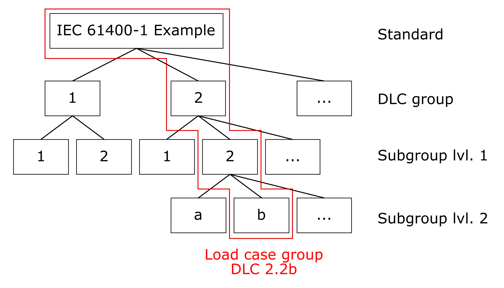
Load Case Groups and Parameter Variation
In general each Standard contains a set of design load case (DLC) groups. Each DLC group can have multiple subgroups. The subgroups are further divided into two levels. Each DLC subgroup level 1 can have multiple level 2 subgroups. With these subdivisions and the concept of parameter variation, it is possible to fully define a complete load simulation for automated processing. Because each combination of DLC groups, subgroups and a variation of parameters usually results in multiple individual load cases (i.e. Analysis Jobs), we call the combination of DLC groups “load case groups”.
In the example to the right, we have two DLC groups 1 and 2. Let us assume that we need two different sets of parameters to represent DLC 1 properly. This could mean that we need to use two different wind field models like the Normal Turbulence Model (NTM) and the Extreme Turbulence Model (ETM). We set up two level 1 subgroups for DLC 1, so we can assign each subgroup the wind model later. The same applies to DLC 2, again there is a need for two subgroups. Assume that within a subgroup, there is another level of variation to be added that cannot easily be set up with parameter variation. A common example is the representation of different fault states or events of the turbine that have to be modelled in different ways. For this, we create level 2 subgroups that inherit all the parameters from the level 1 subgroup.
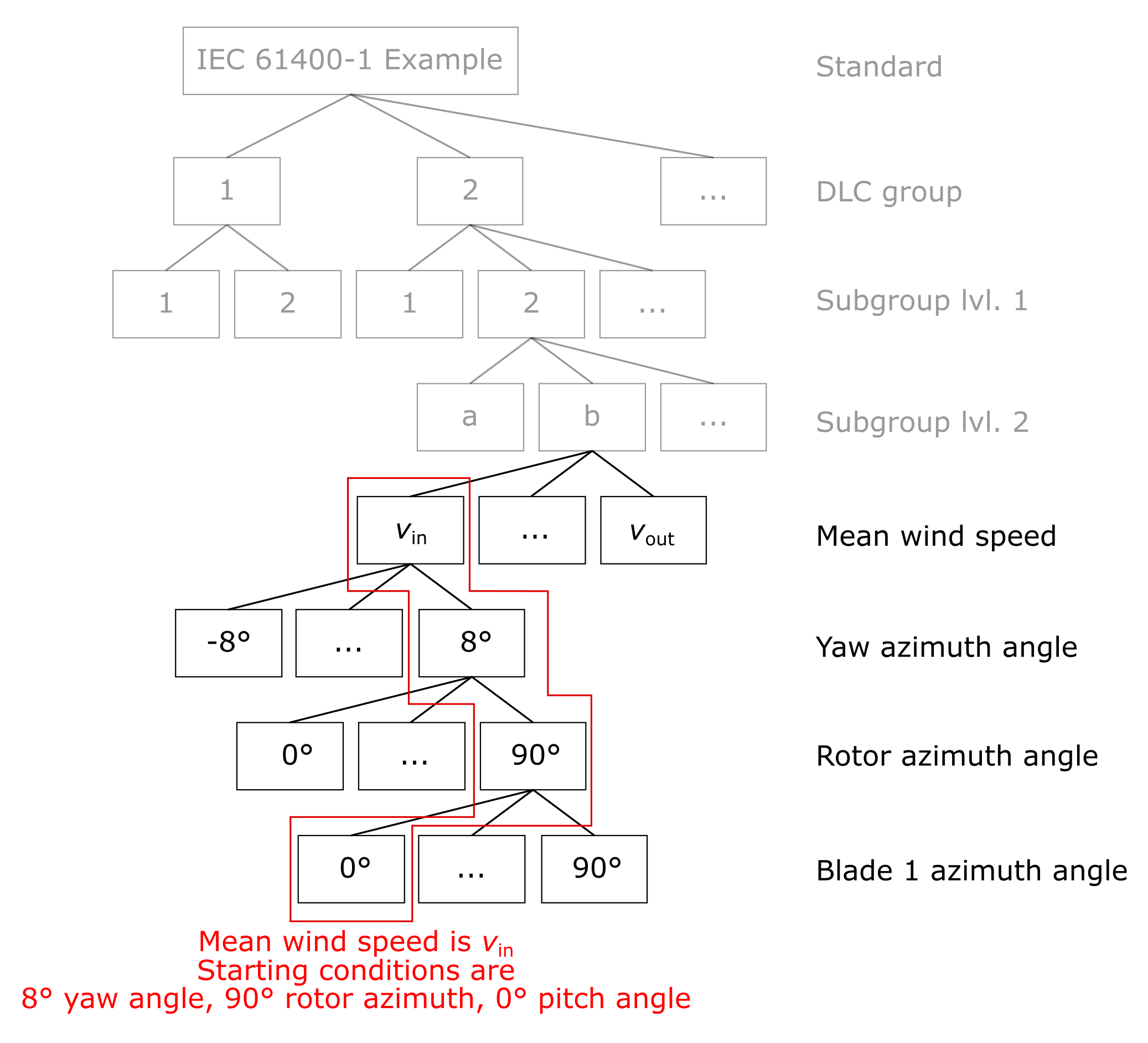
Parameter variation for deriving individual jobs
When the load case groups are set up, PE-Load Prep variates certain Basic Model Parameters (e.g. mean wind speed at hub height) to get a set of Analysis Jobs. That means that we have to specify a range of values that should be considered and spread across individual simulation runs. The most obvious example is the variation of the mean wind speed at hub height, for instance between the cut-in and cut-out wind speeds. In the example to the right, we vary the mean wind speed from the cut-in wind speed \(v_\text{in}\) to the cut-out wind speed \(v_\text{out}\).
Custom DLC Definitions
In the dialog DLC Definitions following columns can be edited:
DLC Group: DLC group name (e.g. ‘1’ for DLC 1.2.a).
DLC Subgroup 1: DLC subgroup name for the first subgroup level (e.g. ‘2’ for DLC 1.2.a).
DLC Subgroup 2: DLC subgroup name for the second subgroup level (e.g. ‘a’ for DLC 1.2.a).
Group Description: Verbose description of main DLC group.
Subgroup 1 Description: Verbose description of DLC subgroup lvl. 1.
Subgroup 2 Description: Verbose description of DLC subgroup lvl. 2.
Initial State: The Initial State determines the initial conditions for each simulation job. The initial conditions are set such that the settling time for the model is kept as short as possible and allows the simulation code to find a solution for the first simulation time step in the first place. The initial conditions are set in the Initialization Job views either manually or as a result of running the Initialization Jobs.
Wind Condition: Wind condition model.
Wind Type (defined by Wind Condition): The Wind Type defines whether a deterministic or a turbulent wind field is used for the job.
Wind Speed Range: Describes for which wind speeds at hub height Analysis Jobs will be created.
Yaw Position Type: Defines for which yaw positions Analysis Jobs will be created.
Rotor Position Type: Defines for which rotor positions Analysis Jobs will be created.
Blade Position Type: Defines for which blade positions Analysis Jobs will be created.
No. of Jobs: Number of Analysis Jobs that only vary regarding the wind field random seed. Defines how many Analysis Jobs will be created per wind speed bin (defined by Wind Speed Range), yaw position (defined by Yaw Position Type), rotor position (defined by Rotor Position Type*) and blade position (defined by Blade Position Type).
To create / delete a new DLC Definition go to Add / Delete. To create, edit and delete Yaw Position Types, Rotor Position Types and Blade Position Types, go to Yaw Pos. Types, Rotor Pos. Types and Blade Pos. Types. Following parameters can be edited for a Yaw Position Types:
Yaw Lower Range End: Lowest yaw angle considered in simulation.
Yaw Upper Range End: Highest yaw angle considered in simulation.
Yaw Increment: Yaw angle interval step size. Jobs will be simulated for yaw angles from Yaw Lower Range End to Yaw Lower Range End with Yaw Increment step size.
Yaw Position Type: Description of considered yaw positions.
Yaw Slippage: Slippage applied to considered yaw angles.
Following parameters can be edited for a Rotor Position Types:
Blade Lower Range End: Lowest blade angle considered in simulation.
Blade Upper Range End: Highest blade angle considered in simulation.
Blade Increment: Blade angle interval step size. Jobs will be simulated for blade angles from Blade Lower Range End to Blade Lower Range End with Blade Increment step size.
Blade Position Type: Description of considered blade positions.
Following parameters can be edited for a Blade Position Types:
Rotor Lower Range End: Lowest rotor angle considered in simulation.
Rotor Upper Range End: Highest rotor angle considered in simulation.
Rotor Increment: Rotor angle interval step size. Jobs will be simulated for rotor angles from Rotor Lower Range End to Rotor Lower Range End with Rotor Increment step size.
Rotor Position Type: Description of considered rotor positions.
In the following the relation between the DLC Definitions and the way Analysis Jobs are created is explained. In PE-Load Prep the Analysis Jobs we want to evaluate are categorized in DLCs (Design Load Cases). To create Analysis Jobs the user defines these DLCs (or use existing DLC definitions) and lets PE-Load Prep create the Analysis Jobs based on these definitions. Let’s assume we have a DLC Definition with the following parameters (et al):
Wind Condition: NTM (turbulent)
Wind Speed Range: v_in < v_hub < v_out (v_prod_ult)
Yaw Position Type: Small yaw error from -8° to 8° in 8° steps
Rotor Position Type: Rotor positions 0°, 30°, 60°, 90°
Blade Position Type: Blade positions from 0° to 90° in 10° steps
No. of Jobs: 1
It says that for every wind speed bin 3 yaw positions, 4 rotor positions, 10 Blade positions and 1 random seed per combination will be considered. Assuming that Vhub Increment is 2 m/s, Vin is 3 m/s and Vout is 20 m/s (see Turbine), then 10 wind speed bins will be considered (in m/s): 3, 5, 7, 9, 11, 13, 15, 17, 19, 20. If you now include this DLC in Analysis Job Configuration PE-Load Prep will in total create 3 x 4 x 10 x 1 x 10 = 1200 Analysis Jobs with the respective yaw positions, wind speeds, etc. that have been defined for the corresponding DLC.
Parameters
Simply put, PE-Load Prep is a powerful text editor that we can teach the logic of standard requirements for the simulation of wind turbines. PE-Load Prep offers a structured approach to the management of parameters. To understand this approach, we need to define some terms and concepts first (see Master Files and Parameter Definition). After that the different types of parameters and their handling are explained (see Global Parameters, Basic Model Parameters, Advanced Model Parameters, Model Parameters and Controller Parameters).
Master Files
A parameter controls the static or dynamic behavior of the turbine model in a situation. A parameter can be a fixed yaw angle, a rotor speed threshold for the control and safety system or a physical constant determining the turbulence in a wind field. Parameters can be found in all of the submodels of the coupled physical model of the wind turbine, which usually consists of several models.
the mechanics, i.e. the structural dynamics and the kinematic contraints,
the wind field,
the aerodynamics of the blades and the aeroelastic coupling,
the control and safety system.
These models are defined by sets of parameters that are stored in master files. The master files are model definition files specific to a simulation software, a software for generating wind fields or a controller model. For each simulation run PE-Load Prep edits parameters in these master files to control the behavior of the model. In this sense, the master files work as templates to be edited for each individual simulation job.
Parameter Definition
A parameter consists of two components: a key and a value. The key is a unique identifier of the parameter found in the master files. The value is a string or numerical value associated with the key that is usually read into and used by the simulation program or one of its components. While the values may change in between simulations, the key is a fixed identifier. In PE-Load Prep, parameters are defined and stored independent of their usage initially. This allows us to use a single parameter in different contexts, e.g. slightly different versions of a controller or a simulation software. The scope of the parameter is however limited to a master file type (which is in turn allocated to one or multiple simulation software or controllers).
The parameter is defined by a unique key name and an optional description. Parameters are allocated a regular expression that indicates the position of the parameter value with respect to its key. If you are not proficient in the use of regular expressions, PE-Load Prep brings pre-defined keywords that cover most of the basic cases you will encounter.
Once we have defined a parameter and how the value is determined for each job, we can control how the value is written to the master file. In most cases, the default value in the master file is found by the regular expression and simply replaced by the correct value. Sometimes, the format of the data as stored in PE-Load Prep has to translated into the format required by the simulation program. For example, the turbulence intensity may have to be expressed as a percentage, such that the value that is stored as a fraction has to be multiplied by 100. Another example would be simple string operations such as quoting strings or replacement of substrings. PE-Load Prep allows you to define a cascade of simple editing operations to parse the stored parameter values for use with a specific simulation program.
As a result the user can fully customize how to parametrize the simulation models of the Analysis Jobs and Initialization Jobs. The parameters of every job can be defined based on static or job specific values by assigning Basic Model Parameters to the Analysis Plan. Further the user can define how to set the parameters of Analysis Jobs based on their affiliation with a DLC by assigning Advanced Model Parameters and Controller Parameters to certain DLCs of the Analysis Plan.
Global Parameters
Global parameters are all parameters in the simulation models that are not edited by PE-Load Prep. They are needed for the simulation model to work, but are the same for all jobs and usually across different Analysis Plans.
Basic Model Parameters
Basic Model Parameters are all parameters that are strictly required for any simulation job to work. These parameters entail wind conditions for the wind field generation and information for the mechanical model such as initial conditions or references to subsidiary model files. Note that Basic Model Parameters are simulation software-specific.
To assign Basic Model Parameters go to Assign Basic Model Parameters in window Workflow or go to Parameters -> Assign Basic Model Parameters in the menu bar. In the following dialog the user can edit how every single Analysis Job / Initialization Job (meaning its simulation model) is going to be parameterized. Note that the displayed list of assigned Basic Model Parameters is Simulation Software specific therefore every change the user makes is applied to all Analysis Plans that have the same Simulation Software assigned to it. Here are the columns that can be edited:
Model Parameter: Model Parameter assigned to the Analysis Plan. Can be changed to any Model Parameter that was created for the same Simulation Software.
Model Parameter Key (defined by Model Parameter): String in Master File to identify the parameter whose value is going to be altered.
Model Parameter Value Syntax (defined by Model Parameter): Regular expression to identify string that represents the model parameter value in the Master File line where Model Parameter Key was found. Can also be a predefined command provided by PE-Load Prep (e.g. first word -> string before first space / tab char in line).
File Description (defined by Model Parameter): Description of Master File (e.g. input file type).
Edit Operation: Describes what type of editing will be applied to the value string identified with Model Parameter Key and Model Parameter Value Syntax.
Execution Order: In case a Model Parameter is assigned more than one time to the current Analysis Plan the user can specify in which order the different edit operations are going to be applied to the respective Model Parameter (must be an integer >= 0).
Value Source: Value with which the Edit Operation is applied to the parameter Model Parameter for every Analysis Job / Initialization Job. This can be a simple string, a General Condition or a Job Specific Condition. (see General Conditions and Job Specific Conditions)
To create, edit and delete Model Parameters go to Edit Model Parameters.
How an assigned Basic Model Parameter affects a job is explained in the following example. Lets’ assume we have the following Basic Model Parameter assigned to the Analysis Plan:
Model Parameter: Hub height
Model Parameter Key: Wind turbine hub-height
Model Parameter Value Syntax: first word
File Description: IECWind v. 5.01.01 (PEC) input file
Edit Operation: replace first
Execution Order: 1
Value Source: general_conditions.hub_height
When PE-Load Prep later on creates the model input files for any job (see Create Input Files for Analysis Jobs and Create Input Files for Initialization Jobs) it will look for the string ‘Wind turbine hub-height’ in ‘IECWind v. 5.01.01 (PEC) input file’. In the identified line it will take the ‘first word’ and replace it with the string represented by ‘general_conditions.hub_height’. ‘general_conditions.hub_height’ equals the Hub Height of the Turbine and assuming that our Hub Height is 67, PE-Load Prep will replace the first word in the first line in ‘IECWind v. 5.01.01 (PEC) input file’, where the string ‘Wind turbine hub-height’ was found, with the string ‘67’.
Let’s assume we have the same Basic Model Parameter (‘Hub height’) assigned a second time with the following setting:
Model Parameter: Hub height
Model Parameter Key: Wind turbine hub-height
Model Parameter Value Syntax: first word
File Description: IECWind v. 5.01.01 (PEC) input file
Edit Operation: add
Execution Order: 2
Value Source: 20
PE-Load Prep will now (according to our parameter assigned with the Execution Order 1) replace the first word in the first line in ‘IECWind v. 5.01.01 (PEC) input file’, where the string ‘Wind turbine hub-height’ was found, with ‘67’. In a second step (according to our parameter assigned with the Execution Order 2) it will take the string ‘67’, convert it back to a number, add 20 to the number (=86) and set the string ‘87’ once again as the first word in the respective line. Obviously this operation is only possible if the Value Source of both assigned Basic Model Parameters (in this case ‘67’ and ‘20’) represent a number.
PE-Load Prep provides the following Edit Operations:
replace first: Replace first captured string with Value Source.
append: Appends Value Source as string to captured string.
prepend: Prepends Value Source as string to captured string.
quote: Adds quotation marks “” to captured string.
translate string: Converts Value Source string using lookup table before further processing.
add: Adds constant number to Value Source (if value is number).
subtract: Subtracts constant number to Value Source (if value is number).
multiply: Multiplies Value Source with constant number (if value is number).
divide: Divides Value Source by constant number (if value is number).
comment switch: Adds (if already there) or removes (if not already there) comment character indicated by Value Source.
replace all: Replace all captured strings with Value Source.
The general conditions subsume all parameters that are not specific to a set of jobs (i.e. specific to a DLC definition or specific to initial states) but are only specific to an Analysis Plan. Within an Analysis Plan, these parameters have equal values for all jobs.
The following General Conditions can be used as Value Source:
analysis_plan_name: Name of Analysis Plan
root_path: Root Path
date_time: Current date and time
user: User
v_in: Vin
v_r: Vr
v_out: Vout
hub_height: Hub Height
rotor_diameter: Rotor Diameter
c_iec: c(ETM)
turbine_class_name: Turbine Class
v_ref: Vref
turbulence_class_name: Turbulence Class
i_ref: Iref
power_law_exponent: Power Law Exponent
vertical_inflow_angle: Vertical Inflow Angle
wind_grid_width: Rotor Diameter + 15
wind_grid_point_number: (Rotor Diameter + 15) / 10
wind_grid_res_skewness: 1
pitch_deviation_blade_1: Pitch Deviation Blade 1
pitch_deviation_blade_2: Pitch Deviation Blade 2
pitch_deviation_blade_3: Pitch Deviation Blade 3
The job-specific conditions subsume all parameters that are specific to a set of jobs and whose values are thus not equal for all jobs. In case of Analysis Jobs, the parameter values depend on the settings specific to the DLC group (or a level of subgroups) as defined in the settings of the Basic Model Parameter, Advanced Model Parameter or Controller Parameter settings. In some cases, the parameter value may be entirely job-specific, such as the random seed parameter for wind field generation. In case of Initialization Jobs, the parameter values depend on the settings specific to the initial state of the DLC group. The initialization cannot be changed by the user but the jobs are handled in the same fashion as the Analysis Jobs. The job-specific conditions usually consist of Basic Model Parameters, Advanced Model Parameters and Controller Parameters.
The following Job Specific Conditions can be used as Value Source:
job_name: Job Name
v_hub: Vhub
t_i: Turbulence intensity of job.
wind_condition_name: Wind Condition
wind_speed_type_name: Any Wind Speed Type
wind_type_name: Wind Type
initial_state_name: Initial State
dlc_group_name: DLC Group
dlc_subgroup_lvl1_name: DLC Subgroup 1
dlc_subgroup_lvl2_name: DLC Subgroup 2
yaw_position: Yaw Position
rotor_position: Rotor Position
blade_position: Blade Position
ini_generator_power: Init Generator Power
ini_rotor_speed: Init Rotor Speed
ini_collective_pitch_angle: Init Collective Pitch Angle
ini_pitch_angle_blade_1: Init Collective Pitch Angle + Pitch Deviation Blade 1
ini_pitch_angle_blade_2: Init Collective Pitch Angle + Pitch Deviation Blade 2
ini_pitch_angle_blade_3: Init Collective Pitch Angle + Pitch Deviation Blade 3
ini_tower_top_displacement_x: Init Tower Top Displ. X
ini_tower_top_displacement_y: Init Tower Top Displ. >
random_seed: Random Seed
t_start: TStart
t_event: TEvent
t_sim: TSim
t_end: TEnd
A complete list of Wind Speed Type strings:
v_prod_ult: The Wind Speed Types control the set of wind speeds that is considered in a DLC group. They can contain a single value or a range of values.
v_prod_fat: This is the range of wind speeds from Vin (Turbine) to Vout (Turbine) in steps of Vhub Increment (Analysis Plan Properties). The range is chosen such that the upper limit of the wind speed bins is selected as mean wind speed as a conservative approach. This range is intended to be used for load cases referring to the Ultimate Limit State.
v_in: Single value, equals Vin (Turbine).
v_out: Single value, equals Vout (Turbine).
v_r: Single value, equals Vr (Turbine).
v_r+2: Single value, equals Vr (Turbine) + 2 m/s.
v_r-2: Single value, equals Vr (Turbine) - 2 m/s.
v_maint: Single value, equals Vmaint (Turbine).
v_ref: Single value, equals Vref (Turbine Class).
v_50: Single value, equals Vref (Turbine Class).
v_1: Single value, equals Vref (Turbine Class) * 0.8.
v_e50: Single value, equals Vref (Turbine Class) * 1.4.
v_e1: Single value, equals Vref (Turbine Class) * 1.4 * 0.8.
0p7v_ref: Single value, equals Vref (Turbine Class) * 0.7.
v_expl_u: This is the range of wind speeds from (including) Vr - 2 m/s (Turbine) to Vout (Turbine) in steps of Vhub Increment (Analysis Plan Properties). The range is chosen such that the upper limit of the wind speed bins is selected as mean wind speed as a conservative approach. This range is intended to be used for load cases used for the statistical extrapolation of 50-year events (DLC 1.1). The subdivision of the production wind speed range is intended to provide a simple means to use DLC subgroups to distribute different numbers of random seeds for different wind regimes.
v_expl_l: This is the range of wind speeds from Vin (Turbine) to (excluding) Vr - 2 m/s (Turbine) in steps of Vhub Increment (Analysis Plan Properties). The range is chosen such that the upper limit of the wind speed bins is selected as mean wind speed as a conservative approach. This range is intended to be used for load cases used for the statistical extrapolation of 50-year events (DLC 1.1). The subdivision of the production wind speed range is intended to provide a simple means to use DLC subgroups to distribute different numbers of random seeds for different wind regimes.
0p8v_ref: Single value, equals Vref (Turbine Class) * 0.8.
v_idle: This is the range of wind speeds from 0 m/s to Vin (Turbine) and from Vout (Turbine) to 0p7v_ref (IEC-type standard) or 0p8v_ref (GL-type standard) in steps of Vhub Increment (Analysis Plan Properties). The range is chosen such that the mean of the wind speed bins is selected as mean wind speed. This range is intended to be used for load cases referring to the Fatigue Limit State.
v_out-2: Single value, equals Vout (Turbine Class) - 2 m/s.
Advanced Model Parameters
Advanced Model Parameters are all parameters that are not required to be edited for all simulation jobs but are usually necessary to represent some load cases. Such parameters may address restrictions of certain degrees of freedom or changes to wind models in certain situations. Note that Advanced Model Parameters are simulation software- and DLC-specific.
To assign Advanced Model Parameters go to Assign Advanced Model Parameters in window Workflow or go to Parameters -> Assign Advanced Model Parameters in the menu bar. In the following dialog the user can edit how every Analysis Job (meaning its simulation model) of a DLC is going to be parameterized (excluding the controller model). The following columns can be edited:
DLC: DLC the Model Parameter is assigned to. Only Analysis Jobs of this DLC will be affected.
Model Parameter: Model Parameter assigned to the Analysis Plan. Can be changed to any Model Parameter that was created for the same Simulation Software.
Model Parameter Key (defined by Model Parameter): String in Master File to identify the model parameter whose value is going to be altered.
Model Parameter Value Syntax (defined by Model Parameter): Regular expression to identify string that represents the model parameter value in the Master File line where Model Parameter Key was found. Can also be a predefined command provided by PE-Load Prep (e.g. first word -> string before first space / tab char in line).
File Description (defined by Model Parameter): Description of Master File (e.g. input file type).
Execution Order: In case a Model Parameter is assigned more than one time to the current Analysis Plan the user can specify in which order the different edit operations are going to be applied to the respective Model Parameter (must be an integer >= 0).
Edit Operation: Describes what type of editing will be applied to the value string identified with Model Parameter Key and Model Parameter Value Syntax.
Model Parameter Value: Value with which the Edit Operation is applied to the parameter Model Parameter for every Analysis Job of DLC. This can be a simple string, a General Condition or a Job Specific Condition. (see General Conditions and Job Specific Conditions)
To create, edit and delete Model Parameters go to Edit Model Parameters.
Advanced Model Parameters are applied in the same way as the Basic Model Parameters with the only difference that Advanced Model Parameters are DLC-specific.
Additionally PE-Load Prep provides Advanced Model Parameter Templates which can be selected under ‘…’ in dialog Assign Advanced Model Parameters or Parameters -> Advanced Model Parameter Template. These templates can be created and deleted as any other Asset and can be edited in the same way as in dialog Assign Advanced Model Parameters. These templates can be shared between Analysis Plans that have the same Simulation Software and Standard assigned. To load the currently assigned template go to Load Current Template.
Model Parameters
To edit Model Parameters go to Parameters -> Model Parameters in the menu bar.
In PE-Load Prep Model Parameters represent all simulation model input parameters that are not associated with controller model. They are used in Assign Basic Model Parameters and Assign Advanced Model Parameters and can be shared between all Analysis Plans that have the same Simulation Software assigned.
Following columns in Edit Model Parameters can be edited:
Model Parameter: Name of Model Parameter.
Model Parameter Key: String in Master File to identify the model parameter whose value is going to be altered.
Model Parameter Value Syntax: Regular expression to identify string that represents the model parameter value in the Master File line where Model Parameter Key was found. Can also be a predefined command provided by PE-Load Prep (e.g. first word -> string before first space / tab in line, second word -> string after first and before second space / tab in line, etc.).
File Description: Description of Master File (e.g. input file type).
To test your own Regular Expressions go to RegExp Tester.
Controller Parameters
Controller Parameters serve the same purpose and are handled in the same way as Advanced Model Parameters with the only difference that they are exclusively affecting the controller model. They are always DLC-specific and are normally used to define and provoke certain operational states in the turbine such as start-up, fault or idling states.
To assign Controller Parameters go to Assign Controller Parameters in window Workflow or go to Parameters -> Assign Controller Parameters in the menu bar. In the following dialog the user can edit how every Analysis Job (meaning its simulation model) of a DLC is going to be parameterized regarding the controller model (in PE-Load Prep Controller Parameters represent simulation model input parameters that are only associated with the controller model).
DLC: DLC the Controller Parameter is assigned to. Only Analysis Jobs of this DLC will be affected.
Controller Parameter: Controller Parameter assigned to the Analysis Plan. Can be changed to any Controller Parameter that was created for the same Controller.
Controller Parameter Key (defined by Controller Parameter): String in Master File to identify the controller parameter whose value is going to be altered.
Controller Parameter Value Syntax (defined by Controller Parameter): Regular expression to identify string that represents the controller parameter value in the Master File line where Controller Parameter Key was found. Can also be a predefined command provided by PE-Load Prep (e.g. first word -> string before first space / tab char in line).
File Description (defined by Controller Parameter): Description of Master File (e.g. input file type).
Execution Order: In case a Controller Parameter is assigned more than one time to the current Analysis Plan the user can specify in which order the different edit operations are going to be applied to the respective Controller Parameter (must be an integer >= 0).
Edit Operation: Describes what type of editing will be applied to the value string identified with Controller Parameter Key and Controller Parameter Value Syntax.
Controller Parameter Value: Value with which the Edit Operation is applied to the parameter Controller Parameter for every Analysis Job of DLC. This can be a simple string, a General Condition or a Job Specific Condition. (see General Conditions and Job Specific Conditions)
To create, edit and delete Controller Parameters go to Edit Controller Parameters.
Additionally PE-Load Prep provides Controller Parameter Templates which can be selected under ‘…’ in dialog Assign Controller Parameters or Parameters -> Controller Parameter Template. These templates can be created and deleted as any other Asset and can be edited in the same way as in dialog Assign Controller Parameters. These templates can be shared between Analysis Plans that have the same Simulation Software and Standard assigned. To load the currently assigned template go to Load Current Template.
To edit Controller Parameters go to Parameters -> Controller Parameters in the menu bar. They can be shared between all Analysis Plans that have the same Controller assigned.
The editing and structure of Controller Parameters is identical to Model Parameters. Following columns in Edit Controller Parameters can be edited:
Controller Parameter: Name of Controller Parameter.
Controller Parameter Key: String in Master File to identify the controller parameter whose value is going to be altered.
Controller Parameter Value Syntax: Regular expression to identify string that represents the controller parameter value in the Master File line where Controller Parameter Key was found. Can also be a predefined command provided by PE-Load Prep (e.g. first word -> string before first space / tab in line, second word -> string after first and before second space / tab in line, etc.).
File Description: Description of Master File (e.g. input file type).
To test your own Regular Expressions go to RegExp Tester.
Jobs
There a two kinds of simulation jobs in an Analysis Plan: Initialization Job and Analysis Job. An Analysis Job represents a single simulation run. It contains a set of parameters that control how the turbine model behaves in that simulation run. PE-Load Prep creates a folder for each Analysis Job and stores all files that are required to run the simulation in that folder. PE-Load Prep also sets up all subprocesses needed within a simulation run, for instance the simulation of a wind field before the turbine simulation. Finally, we can monitor the progress of the simulation runs and get a feedback if each run was successful or if an error has occurred.
Initialization Jobs are basically the same as Analysis Jobs, but have a special task in the PE-Load Prep workflow. Initialization Jobs are automatically derived from the Analysis Jobs currently set up within an Analysis Plan. They are used to find adequate initial conditions for the Analysis Jobs to reduce the settling time. They contain a limited set of parameters that represent a simple simulation under quasi-steady conditions. The run is intended to find the steady-state of the turbine model for these conditions. PE-Load Prep extracts some of the steady-state conditions and sets them as parameters for the Analysis Jobs. You can chose to use the PE-Load Prep initialization process, set the parameters manually or simply ignore this step.
Every Initialization Job and Analysis Job created by PE-Load Prep is displayed in the window Jobs. The jobs are categorized by their Initial State / DLC main group, that is for every group a tab is created. Furthermore in tab Overview a statistical summary for every DLC and Initial State group is provided based on the Status of every job. Here the user can apply changes (regarding the columns Status and Included) to jobs of whole groups by using the context menu.
Every job has ony of the following Status:
planned: A newly created job starts with the status planned. When the user Creates Input Files for Initialization Jobs / Creates Input Files for Analysis Jobs a job folder with the associated model input files is created for every job for which Included is checked and that has the status planned. Afterwards PE-Load Prep sets their status to prepared.
initialized: Only available for Analysis Jobs. If a Initialization Job has been successfully simulated in Job Queue and the initial conditions have been retrieved (Import Initial Conditions) the status of every Analysis Job that is associated with the Initialization Job and whose former status was planned will be set to initialized. When the user Creates Input Files for Analysis Jobs a job folder with the associated model input files is created for every job for which Included is checked and that has the status initialized (as with status planned). Afterwards PE-Load Prep sets their status to prepared.
prepared: Status of jobs for which input files have been created. When the user goes to Add Initialization Jobs to Queue / Add Analysis Jobs to Queue every job for which Included is checked and that has the status prepared will be sent to the Job Queue. Afterwards PE-Load Prep sets their status to in queue.
in queue: Status of job that have been sent to the Job Queue.
analyzed: The status of jobs that have been successfully simulated in Job Queue will be set to analyzed.
fault: The status of jobs whose simulation in Job Queue has failed will be set to fault.
The Status of a job can be manually altered. To show / hide the window Jobs go to View -> Jobs.
Initialization Jobs
Initialization Jobs are used to determine the initial conditions of Analysis Jobs. When the user creates / deletes Analysis Jobs by including / excluding DLCs in Analysis Job Configuration, PE-Load Prep automatically creates / deletes the appropriate Initialization Jobs that are used to determine the initial conditions of the respective Analysis Jobs: For every existing combination of Vhub, Yaw Position and Rotor Position within the Analysis Jobs a Initialization Job is created, that uses the Wind Condition NWP and has a simulation time of 100 seconds.
Following columns regarding Initialization Jobs are displayed:
Include: Set checked if you want to include the job for further processing (e.g. Create Input Files for Initialization Jobs, Add Initialization Jobs to Queue, etc.)
Status: Job status that determines if the job is set for further processing (e.g. only jobs with Status ‘prepared’ and that are Included will be sent to the Job Queue if you Add Initialization Jobs to Queue). Can be manually altered.
Job Name: This is a unique identifier for a single job. This string is used to name the job folder and the edited master files in the job folder.
Initial State Short Name: The Initial State Shirt Name is an identifier and only used in the job name string.
Vhub: This is the mean longitudinal wind speed at hub height. This parameter is usually used by the wind field generation program in the Basic Model Parameters. This parameter is used to allocate the initial conditions for the respective wind speeds to jobs with the same wind speeds.
Wind Condition: The Wind Condition is an identifier for the wind model to be used by the wind field generation program. The Wind Condition is usually translated into a string readable by the wind field generation program as defined in the Basic Model Parameters for the respective Simulation Software. The Wind Condition is NWP for all Initialization Jobs and cannot be changed.
Wind Type: The Wind Type defines whether a deterministic or a turbulent wind field is used for the job. The Wind Type is used in addition to the Wind Condition in cases where the wind field generation program requires this additional information or to determine which wind field generation program is used to create the wind field. The Wind Type is constant for all Initialization Jobs and cannot be changed.
Yaw Position: The Yaw Position for Initialization Jobs is used as initial condition for the Initialization Job on the one hand and the allocation of the initial conditions for the respective wind speeds to jobs with the same starting Yaw Position.
Rotor Position: The Rotor Position for Initialization Jobs is used as initial condition for the Initialization Job on the one hand and the allocation of the initial conditions for the respective wind speeds to jobs with the same starting Rotor Position.
Collective Blade Position: The Collective Pitch Position for Initialization Jobs is used as initial condition for the Initialization Job on the one hand and the allocation of the initial conditions for the respective wind speeds to jobs with the same starting Collective Pitch Position.
TStart: Settling-in time of jobs. Time after which the actual simulation starts (See Simulation Time Template.)
TEvent: Event duration of jobs. Duration of any special event (applies only if event is defined for respective DLC, See Simulation Time Template.).
TSim: Duration of simulation (See Simulation Time Template.)
TEnd: TEnd = TStart + TSim (See Simulation Time Template.)
Init Collective Pitch Angle: This is the average pitch angle for all the blades during the last TSim seconds of the initialization run. The parametercan be used to set the initial pitch angle for the simulation program.
Init Generator Power: This is the average generator power during the last TSim seconds of the Initialization run. The initial generator power can be used to derive starting torque for the simulation program.
Init Rotor Speed: This is the average rotor speed during the last TSim seconds of the initialization run. The parameter can be used to set the initial rotor speed for the simulation program.
Init Tower Top Displ. X: This is the tower top displacement in longitudinal direction during the last TSim seconds of the initialization run. The parameter can be used to set the tower top displacement for the simulation program.
Init Tower Top Displ. Y: This is the tower top displacement in lateral direction during the last TSim seconds of the initialization run. The parameter can be used to set the tower top displacement for the simulation program.
To create input files for Initialization Jobs go to Create Input Files for Initialization Jobs in window Workflow or Jobs -> Create Input Files for Initialization Jobs in the menu bar.
To send Initialization Jobs to the Job Queue go to Add Initialization Jobs to Queue in window Workflow or Jobs -> Add Initialization Jobs to Queue in the menu bar.
If a Initialization Job has been successfully simulated in Job Queue the user can retrieve the initial conditions by going to Import Initial Conditions in the context menu or Jobs -> Import Initial Conditions in the menu bar. Subsequently the initial condition columns (Init Collective Pitch Angle, Init Generator Power, etc.) of the respective job will be updated. These columns can also be manually edited.
Analysis Jobs
Analysis Jobs are the jobs we actually want to evaluate. The user can create / delete Analysis Jobs by including / excluding the respective DLCs in Analysis Job Configuration.
Following columns regarding Analysis Jobs are displayed:
Include: Set checked if you want to include the job for further processing (e.g. Create Input Files for Analysis Jobs, Add Analysis Jobs to Queue, etc.)
Status: Job status that determines if the job is set for further processing (e.g. only jobs with Status ‘prepared’ and that are Included will be sent to the Job Queue if you Add Analysis Jobs to Queue). Can be manually altered.
Job Name: This is a unique identifier for a single job. This string is used to name the job folder and the edited master files in the job folder.
DLC Group: This is the DLC group name. Used to identify the DLC folder. (e.g. ‘1’ for DLC 1.2.a).
DLC Subgroup 1: This is the DLC Subgroup Name for the first subgroup level. Used to identify the DLC folder. (e.g. ‘2’ for DLC 1.2.a).
DLC Subgroup 2: This is the DLC Subgroup Name for the second subgroup level. Used to identify the DLC folder. (e.g. ‘a’ for DLC 1.2.a).
Vhub: This is the mean longitudinal wind speed at hub height. This parameter is usually used by the wind field generation program in the Basic Model Parameters.
Wind Condition: The Wind Condition is an identifier for the wind model to be used by the wind field generation program. The Wind Condition is usually translated into a string readable by the wind field generation program as defined in the Basic Model Parameters for the respective Simulation Software.
Wind Type: The Wind Type defines whether a deterministic or a turbulent wind field is used for the job. The Wind Type is used in addition to the Wind Condition in cases where the wind field generation program requires this additional information or to determine which wind field generation program is used to create the wind field.
Initial State Short Name: The Initial State determines the initial conditions for each simulation job. The initial conditions are set such that the settling time for the model is kept as short as possible and allows the simulation code to find a solution for the first simulation time step in the first place. The initial conditions are set in the Initialization Job views either manually or as a result of running the Initialization Jobs. For more information see Initialization Job.
Yaw Position: The Yaw Position for Analysis Jobs is used as initial condition for the starting Yaw Position.
Rotor Position: The Rotor Position for Analysis Jobs is used as initial condition for the starting Rotor Position.
Blade Position: The Blade Position for Analysis Jobs is used as initial condition for the starting Pitch Position.
Random Seed: Random seed for calculation of turbulent wind field. PE-Load Prep automatically assigns a Random Seed to every Analysis Job but it can be manually altered.
TStart: Settling-in time of jobs. Time after which the actual simulation starts (See Simulation Time Template.)
TEvent: Event duration of jobs. Duration of any special event (applies only if event is defined for respective DLC, See Simulation Time Template.).
TSim: Duration of simulation (See Simulation Time Template.)
TEnd: TEnd = TStart + TSim (See Simulation Time Template.)
Last Change: Date and time of last change.
Last Change By: User who made the last change.
To create input files for Analysis Jobs go to Create Input Files for Analysis Jobs in window Workflow or Jobs -> Create Input Files for Analysis Jobs in the menu bar.
To send Analysis Jobs to the Job Queue go to Add Analysis Jobs to Queue in window Workflow or Jobs -> Add Analysis Jobs to Queue in the menu bar.
When the initial condition have been set / imported for the associated Initialization Job (see column Init Collective Pitch Angle, Init Generator Power, etc. in tables of Initialization Jobs) they will be applied when the user creates the input files for the respective Analysis Jobs (Create Input Files for Analysis Jobs). Otherwise the initial conditions will be set to 0. To find the associated Initialization Job of a given Analysis Job go to the tab with same Initial State and look for the appropriate combination of Vhub, Yaw Position and Rotor Position.
Job Queue
The Job Queue provides all the necessary means to start and monitor the simulation of wind and solver tasks. For every Initialization Job / Analysis Job that has been sent to the Job Queue (see Add Initialization Jobs to Queue and Add Analysis Jobs to Queue) PE-Load Prep creates two Job Tasks: A task to compute the wind field and a task to simulate the actual job (solver task). These tasks and their properties will be subsequently displayed in window Job Queue:
Job Name: Name of Analysis Job / Initialization Job for which the Job Task was created.
Job Task Type: Software with which the Job Task will be simulated (e.g IECWind for calculation of wind field, OpenFAST as solver for the simulation).
Task Status: Status of task. Can be manually altered. Following status entries are available:
pending: Task will be considered when Job Queue has been started (see Start Queue).
running: Task is currently being processed.
finished: Task has been successfully simulated.
fault: Simulation of task has failed.
Last Message: Last monitoring message (e.g. ‘output file is missing’)
To start the simulation of the displayed tasks go to Start Queue (likewise Stop Queue to stop). PE-Load Prep will subsequently launch the simulation of every task (in the displayed order) that has the status pending. The task order can be changed by the user (see buttons |<, <, >, >|) but note that tasks that are interdependent (e.g. wind and solver task of the same Analysis Job) always have to be processed in the same order.
The maximum number of tasks that are going to be processed at the same time and other options regarding the task monitoring can be edited in Settings. If the wind and the solver task of a job have been successfully simulated PE-Load Prep will set the Status of the job in Jobs to analyzed (otherwise to fault). To display these changes go to Refresh Job Status in the context menu of window Jobs. Every error detected by the monitor will be displayed in the column Last Message of the respective Job Task.
If Reuse Wind Fields in Settings is checked PE-Load Prep will save every turbulent wind field that has been successfully created in Job Queue. When the user sends an Analysis Job to the Job Queue (see Add Analysis Jobs to Queue) PE-Load Prep will check if an appropriate wind field already has been simulated. If a wind field with same general parameters (e.g. Vhub) exists it will be assigned. If a wind field fits more than one Analysis Job that has been sent to the Job Queue PE-Load Prep will assign the wind field to the job with same Random Seed.
If Use Scratch Folder for Simulation in Settings is checked the simulation of every Job Task will be executed under Scratch Folder Path. If this applies PE-Load Prep will do the following steps for every Job Task: 1. All model files will be copied to the provided Scratch Folder, 2. Simulation will be launched in Scratch Folder, 3. Model and created result files will be copied back to to the original directory under Root Path after the simulation has finished (or if it has aborted).
To remove all entries from the Job Queue go to Clear Queue. To show / hide the window Job Queue go to View -> Job Queue.